
Indirect Fired Bath Heaters
Horizontal water-bath heaters that bring high-viscosity, high-water-cut crude up to treating temperature — safely, evenly and without hot-spotting the process fluid. Engineered, fabricated and commissioned worldwide by Howe Baker International.
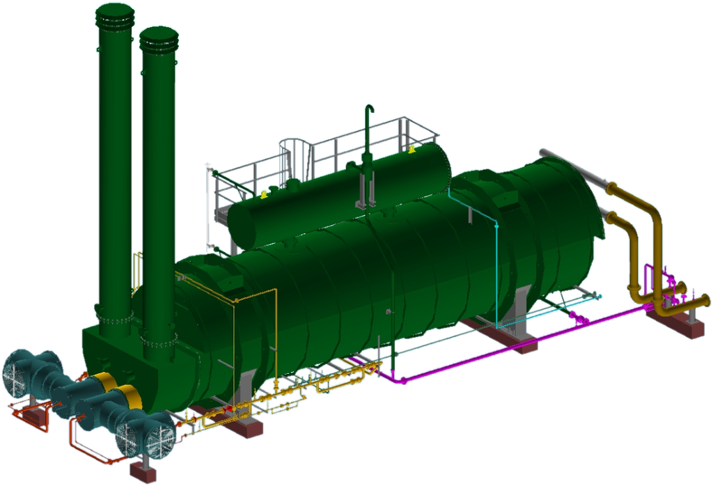
Why oilfields heat their crude first
Crude arrives at the gathering station as a cold, viscous emulsion of oil, produced water and salt. Before it can be sold — or even pumped economically — it has to be conditioned. Heating is the first and most important step.
Cut the viscosity
Raising the emulsion from ambient to 60–65 °C collapses its viscosity by an order of magnitude. Pumps work less, pipelines flow faster, and the tight oil-water emulsion begins to destabilise.
Break the emulsion
Heat weakens the films that hold water droplets dispersed in the oil. Combined with demulsifier chemistry, free water separates and the crude becomes treatable.
Finish electrostatically
The heated crude then passes to an electrostatic coalescer, where a high-voltage field coalesces the remaining droplets — removing the last of the water and dissolved salt to sales specification.
Indirect heating: the bath does the work
A gas-fired burner fires into large-bore fire tubes immersed in a water/glycol bath. The bath — held near 95 °C at atmospheric pressure — transfers heat gently to a multi-pass process coil carrying the crude. The flame never sees the process fluid.
- No hot-spots, no coking — coil wall temperature can never exceed the bath temperature, regardless of burner firing.
- Intrinsically safer — a coil leak enters a near-atmospheric water bath, not a firebox.
- API Spec 12K throughout — fire-tube heat flux held within 10,000–12,000 BTU/hr·ft² and burner heat-release density within 15,000 BTU/hr·in².
- Glycol bath options — MEG/water mixtures selected automatically for boiling margin and site freeze protection.
- Removable fire-tube sections — twin independent firebox sections with their own smoke-tube return banks for on-line flexibility and easy pull-out.
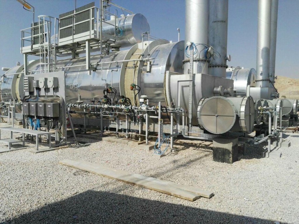
Burner front: low-NOx burners, double block-and-bleed fuel trains, FD windbox and smoke-box returns
Natural draft or forced draft — engineered either way
Draft is the pressure that pulls combustion products through the fire tubes and up the stack. How you create it defines the machine.
The stack does the pulling
Hot flue gas is lighter than ambient air; a properly sized stack creates enough buoyant draft to overcome fire-tube and stack friction on its own.
- No rotating equipment, no power demand — ideal for remote wellsites
- Stack height & diameter iterated until the draft balance closes, with site elevation honoured (API 12K §4.6)
- Turndown and wind sensitivity must be respected in design
Fans take control
FD fans (typically 2 × 100%, one working, one standby) push combustion air through a windbox and low-NOx burner, making draft independent of weather and firing rate.
- Precise excess-air control → higher efficiency, lower NOx
- Compact stacks — the fan supplies the losses, the stack handles dispersion
- Full draft balance published: stack + fire-tube buoyancy vs friction, velocity head and margin
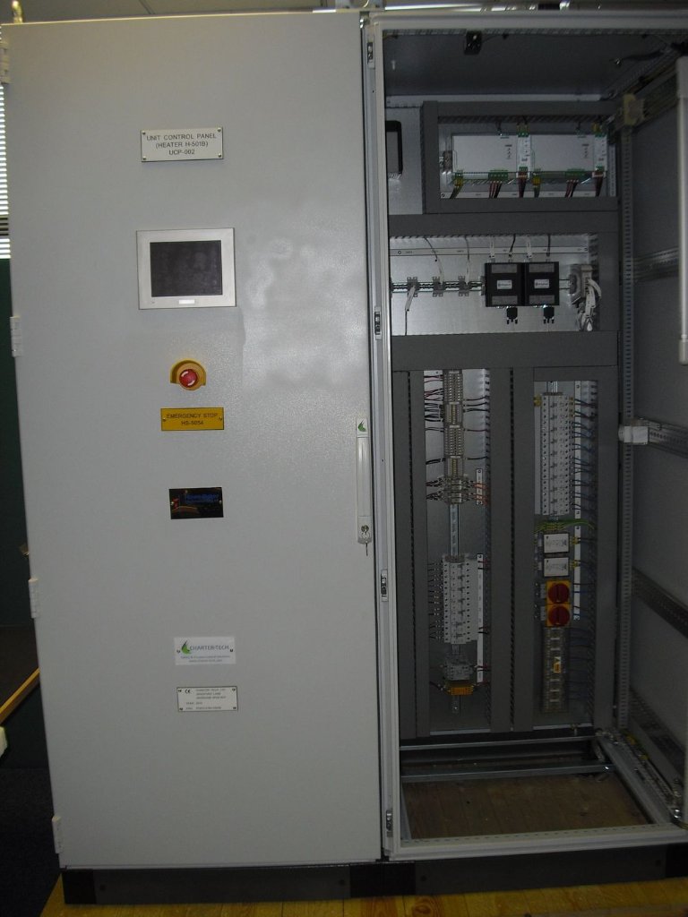
Unit Control Panel (UCP) — PLC-based BMS with HMI, shown as installed
PLC-controlled from purge to full fire
Every heater ships with its own Unit Control Panel: a PLC-based Burner Management System engineered to IEC 61511 principles, with an HMI touchscreen, hardwired emergency stop and SIL-rated trip loops.
- Automatic purge, pilot ignition, flame proving and main-gas sequencing
- UV main-flame scanner and ionisation pilot detection
- Bath temperature, level and low-low protections; fire-tube skin temperature monitoring
- FD fan control with auto-changeover to standby; damper and excess-air trim
- Double block-and-bleed fuel-gas trains with proof-of-closure valves
- Remote DCS/SCADA interface — Modbus, hardwired trips, or OPC UA
Designed in 3D before a single plate is cut
Every package is fully modelled: vessel, fire tubes and smoke-tube banks, coil bundle with its U-bend serpentine routing, burner skids, ducting, stacks, ladders and platforms. The model drives everything downstream.
- Clash-free layout — piping, valve trains and instrument access proven before fabrication
- Coil bundle packed algorithmically: equal header spacing, U-bend pitch grid, 100 mm shell clearance, exits in a single top row
- Fire-tube bore and smoke-tube banks size-optimised for lowest weight while holding API 12K flux and heat-release limits
- Draft balance, stack sizing, FD fan duty, glycol selection and expansion tank all computed from one engine — datasheet and GA produced from the same run
- Client review models and as-built deliverables in native or neutral CAD formats
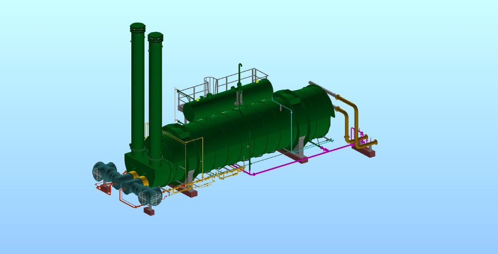
Full-package 3D model: shell, twin stacks, FD fans, expansion tank, fuel trains and access platforms
Engineered clause-by-clause to API Spec 12K
API Specification 12K, Indirect Type Oilfield Heaters, governs how these machines must be designed, fabricated, tested and marked. Our sizing engine does not treat it as a checklist at the end — every limit is built into the design iteration itself, and every run prints the actual value against the allowable.
Fire-tube heat flux
Average heat flux on the exposed fire-tube surface is held within 10,000–12,000 BTU/hr·ft² for glycol/water baths. The engine caps the allowable at the code’s upper bound and sizes the fire-side surface so the actual flux lands just under it — reported in kcal/m²·hr and BTU/hr·ft² on the datasheet.
Heat-release density
Burner heat release through the fire-tube cross-section is limited to 15,000 BTU/hr·in². This sets the minimum fire-tube bore — our optimiser starts at that minimum and iterates upward, so compliance is guaranteed by construction, never by luck of an input.
Stack & draft
Stack height must generate draft sufficient to overcome fire-tube, return and stack losses — with site elevation considered. The published draft balance lists buoyant draft available vs friction, velocity head and margin, using elevation-corrected atmospheric pressure.
Coil working pressure
Process coils follow the code’s working-pressure basis: pipe wall verified against design pressure on a B31 formula with 12.5% mill tolerance and full corrosion allowance — checked for every pipe size and schedule the optimiser considers.
Fabrication & testing
Coil welding to ASME IX qualified procedures; shells, fire tubes and stacks fabricated and leak-tested per the specification; hydrostatic testing of coils witnessed and documented. Bath shells designed to ASME VIII Div 1 where rated.
Marking & documentation
Nameplates carry the firebox rating, fire-tube surface area and design data the code requires. Each unit ships with its datasheet, draft calculation, coil layout and performance basis — generated from the same engineering run that sized it.
Companion codes on every package
ASME Section VIII Div 1 — bath vessel · ASME B31.3 — process coil & headers · ASME IX — welding · IEC 61511 — SIL-rated burner management · IEC 60079 / ATEX — hazardous-area electrical · ISO 9001 — quality management
Have an emulsion to heat?
Send us your flows, temperatures and fuel gas — we will return a sized heater, datasheet, section drawings and draft balance, engineered to API Spec 12K.
Contact Howe Baker International