
Electrostatic Coalescer Pre-Wash
Howe Baker designs and supplies DC electrostatic coalescers for the caustic prewash section of kerosene Merox units — and adapts, retrofits, troubleshoots and re-parts the electrostatic coalescers and precipitators already installed on site, including units whose original manufacturer no longer exists.
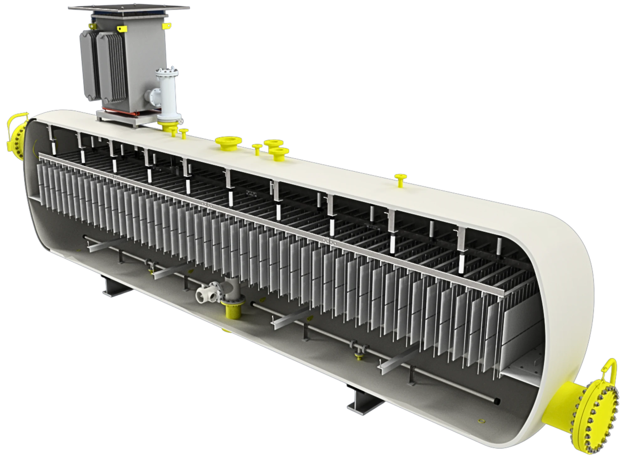
Vertical DC treater, cutaway — transformer/rectifier power unit on the top platform, proprietary entrance bushing through the top head, inlet distributor below the proprietary electrostatic grid and above the caustic interface.
About This Solution
In a kerosene Merox unit, the caustic prewash removes hydrogen sulphide and naphthenic acids upstream of the mercaptan-oxidation reactor. The kerosene leaves the prewash contactor carrying a fine, stable dispersion of spent caustic. If that caustic carries over, it fouls the Merox catalyst bed, consumes fresh caustic, raises the sodium content of the product and puts the jet fuel water-separation and haze specifications at risk.
Howe Baker applies Direct Current (DC) electrostatic treater technology to resolve that dispersion. A high-voltage DC field applied across Howe Baker's proprietary electrostatic grid polarises the entrained caustic droplets so that they coalesce and settle, reducing the aqueous phase in the kerosene to ppm levels. Because kerosene has very low electrical conductivity, fields of 20,000–40,000 volts can be sustained continuously — the condition that makes electrostatic coalescence so much more effective than gravity settling or coalescer media alone in this service.
The same DC treater platform has been supplied for gas condensate, LPG, naphtha, jet fuel, kerosene and diesel dehydration, so the prewash coalescer can be specified from a proven design rather than developed from first principles.
Where This Solution Is Used
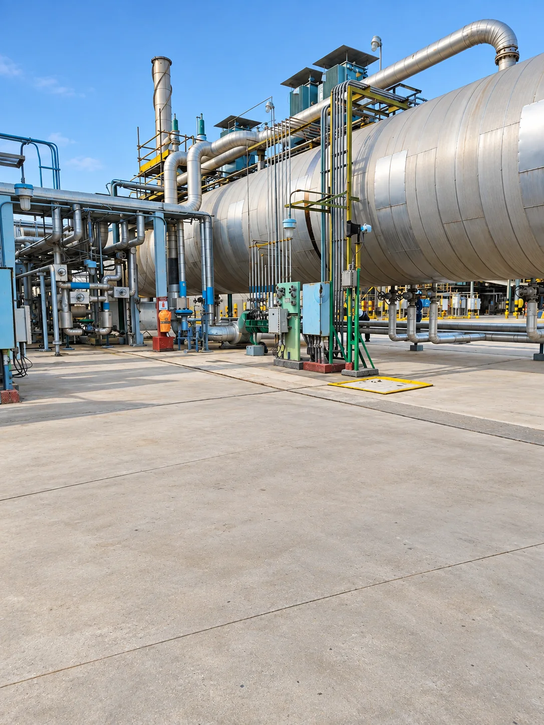
The prewash coalescer sits between the caustic prewash contactor and the Merox reactor. These are the duties it is asked to carry.
Caustic Carryover Removal
Separation of entrained spent caustic from prewashed kerosene before the Merox reactor, protecting the catalyst bed and holding down fresh caustic make-up.
Sodium Control in Jet Fuel
Reducing dissolved and dispersed caustic so that sodium and water-reaction limits in Jet A-1 / DEF STAN 91-091 and ASTM D1655 product are met downstream.
Haze and Water-Separation Protection
Bringing the aqueous phase down to ppm levels so that the product passes haze rating and MSEP / water-separation tests after Merox sweetening and clay treating.
Replacing Undersized Settlers
Where a gravity settler or coalescer-media vessel cannot keep up with increased throughput or a tighter emulsion, the DC field restores separation without a larger vessel.
Merox Catalyst Life Extension
Fewer caustic and water slugs reaching the reactor means fewer catalyst upsets and longer runs between bed change-outs.
Post-Merox Caustic Settling
The same DC treater design can be applied on the reactor effluent side of the unit where caustic settling is the limiting step.
Flow Distribution Verified by CFD
The single biggest threat to electrostatic performance is turbulence and maldistribution at the inlet. A jet of kerosene that channels through one part of the electrostatic grid shortens residence time there, re-entrains caustic that has already settled, and leaves the rest of the field under-used. Howe Baker therefore designs the low-pressure-drop inlet distributor and outlet collector using Computational Fluid Dynamics (CFD) modelling of the whole vessel.
The CFD computation resolves the velocity field from the inlet nozzle, through the distributor and up through the proprietary electrostatic grid to the product outlet, together with the caustic droplet trajectories and the behaviour of the liquid/liquid interface. The distributor geometry, hole pattern and position relative to the grid are iterated until the model shows uniform upward velocity across the full grid cross-section, no short-circuiting to the outlet, and no disturbance of the settled caustic layer.
- Velocity uniformity across the electrostatic grid and residence-time distribution
- Droplet settling trajectories and interface stability under the design and turndown cases
- Pressure drop across distributor and collector internals
- On retrofits: the existing vessel and nozzles are modelled first, so new internals are designed against the flow field you actually have
Howe Baker's Engineering Role
Efficient electrostatic separation depends on the inter-relationship between every component of the treater. Each one is designed and optimised together.
Power Units
A low-voltage three-phase AC supply is stepped up and rectified in a transformer/power unit to give a virtually constant single-phase DC output. Two features matter in service: the unit is fully reactive, so the electrical supply cannot be overloaded and the treater stays online through adverse conditions; and a separate voltage controller on the local panel lets the operator select the optimum electrode voltage across the full range.
Proprietary Entrance Bushing
Howe Baker's proprietary entrance bushing carries the high-voltage supply from the power unit outside the vessel to the electrostatic grid inside it. PTFE is used as the insulating material for both the entrance bushing and the grid insulators, designed for the temperature and elevated pressure that the prewash service can demand.
Proprietary Electrostatic Grid
Howe Baker's proprietary electrostatic grid, in a vertical configuration, gives an open, free-flowing regime throughout the electrostatic field. The size, orientation and location of the grid within the vessel are the critical design variables and are set for the specific caustic-in-kerosene duty.
Fluid Distribution
Low-pressure-drop inlet distribution and outlet collection systems minimise turbulence, spread the inlet stream evenly into the electrostatic grid and give an even draw-off of caustic and product. The inlet is introduced below the electrostatic grid, which sits above the normal liquid/liquid interface, and the distributor design is verified by CFD computation of the flow field inside the vessel.
Operating Conditions
Operating conditions follow those available from the prewash contactor. The operating pressure is set high enough to prevent vaporisation of the kerosene being processed, and the electrical design meets the hazardous area classification of the Merox unit location.
Packaging
Units are supplied in vertical or horizontal configuration. As prewash coalescers are relatively small, most clients take them as fully modular, skid-mounted packages with piping and local control panel, ready for quick site installation and tie-in to the existing unit.
Kero-Merox Prewash — Process Detail
Already Have an Electrostatic Coalescer or Precipitator Installed?
Many Merox units run electrostatic coalescers or precipitators that were supplied decades ago, often by a manufacturer that has since closed, been absorbed or left the business. When the original vendor is gone, the unit does not have to be. Howe Baker will look into what you have, adapt our design to fit it, and support it for the rest of its life.
We adapt our design to your installation
We review the existing vessel, nozzles, electrode arrangement, bushings and power supply — from your drawings, a site survey, or both — and engineer a retrofit that fits the installation you already have.
- Howe Baker proprietary electrostatic grid and PTFE insulators sized to the existing shell
- Proprietary entrance bushings matched to existing nozzles
- New fully reactive transformer/power unit with variable voltage control
- Inlet distributor and outlet collector upgrades within the existing vessel, designed from a CFD model of your shell and nozzles
- Conversion of an ageing precipitator or settler to a DC treater
We diagnose units that are underperforming
Caustic carryover, tripping power units, low field voltage, interface control problems and short catalyst runs usually trace back to a small number of causes. We help you find which one.
- Electrical: entrance bushing tracking, insulator failure, power unit and voltage controller faults
- Process: flow maldistribution (checked by CFD of the existing internals), interface level, temperature and conductivity effects
- Mechanical: grid alignment, distributor damage, fouling
- Performance testing and acceptance criteria for water and caustic content
We source or engineer spares to suit your unit
When the original manufacturer no longer exists, the spares list disappears with them. We will look into what is available and, where the original part cannot be had, engineer a replacement to suit your installation.
- Proprietary entrance bushings and grid insulators
- Electrostatic grid assemblies, hangers and support components
- Transformer/power units, rectifiers and voltage controllers
- Distributor and collector internals
- Reverse-engineering from drawings or the worn part where no data survives
A vessel data sheet, nameplate photograph and any surviving drawings are enough for a first assessment.
What We Look At First
The first pass on any existing installation covers the items below. Most can be answered from drawings and operating records before anyone visits site.
Related Projects
Vertical Electrostatic Coalescer
Vertical DC electrostatic coalescer supplied for distillate treating duty, delivered as a modular skid-mounted package with piping and local control panel.
Speak to Howe Baker About Your Merox Prewash
Whether you are specifying a new prewash coalescer or keeping an orphaned unit running, our engineering team can assess your requirements and advise on the most appropriate design, retrofit scope, spares and delivery model.
Start a Project Enquiry