Sulfur recovery refers to the conversion of hydrogen sulfide (H2S) to elemental sulfur. Hydrogen sulfide is a by-product of processing natural gas and refining high-sulfur crude oils. There are many sulfur recovery technologies available for different applications, however the most common conversion method used is the Claus process. Approximately 90 to 95 percent of recovered sulfur is produced by the Claus process. The Claus process typically recovers 95 to 98 percent of the hydrogen sulfide feedstream. Only the Claus process will be described here, however please contact SRE for information related to any sulfur recovery process.
Howe-baker Claus Sulfur Recovery Process
HYDROGEN SULFIDE (H2S)
SYNONYMS: SOUR GAS OR ACID GAS
- ‘Sour Gas’ is commonly present in natural gas and oil formations.
- At low concentrations, it smells like rotten eggs
- EXTREMELY dangerous as it is heavier than air, impairs our ability to smell/detect with increasing concentration, and exposure to >500 ppm can be fatal!
- With respect to safety and product specifications, it must be removed from natural gas and petroleum products.
Thus, how do we safely rid ourselves of H2S and make another potentially valuable product?
THE SULFUR RECOVERY UNIT (SRU)
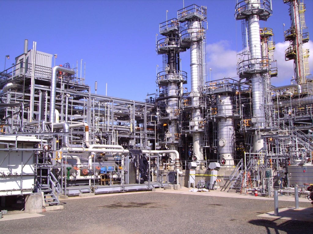
The Sulfur Recovery Unit (SRU) is based on the modified Claus Process, which is a two-step reaction scheme overall. A portion of the total H2S is burned in the Reaction Furnace to form SO2. Then, the H2S and SO2 react, at an optimal 2:1 ratio, to form elemental Sulfur (Sx) across the Claus Reactors. After each catalytic stage, liquid sulfur is recovered in the Claus Condensers. The remaining unreacted H2S and SO2 then proceed to the next stage, where the equilibrium-limited Claus reaction continues in the presence of Claus catalyst.
MEETING SULFUR RECOVERY REQUIREMENTS
In general, gas processing plants and oil refineries are required to recover between 95 and 99.99 percent of the total sulfur introduced to the SRU. A conventional 2-stage SRU, with two Claus Reactors, is typically expected to recover 96+ percent. For a 3-stage SRU, the general expectation is 98+ percent. If necessary, a Tail Gas Cleanup Unit (TGCU) is required to recover the remainder.
Emissions regulations are only becoming more stringent each and every year! That’s where SRE can help out. Our specialized testing services ensure that the operation of your SRU is optimized for long-term performance and reliability purposes!
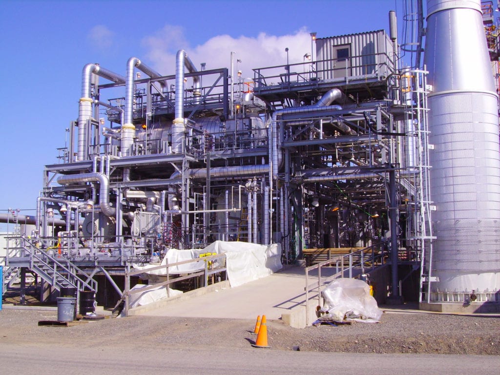
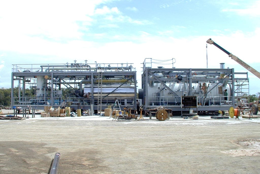
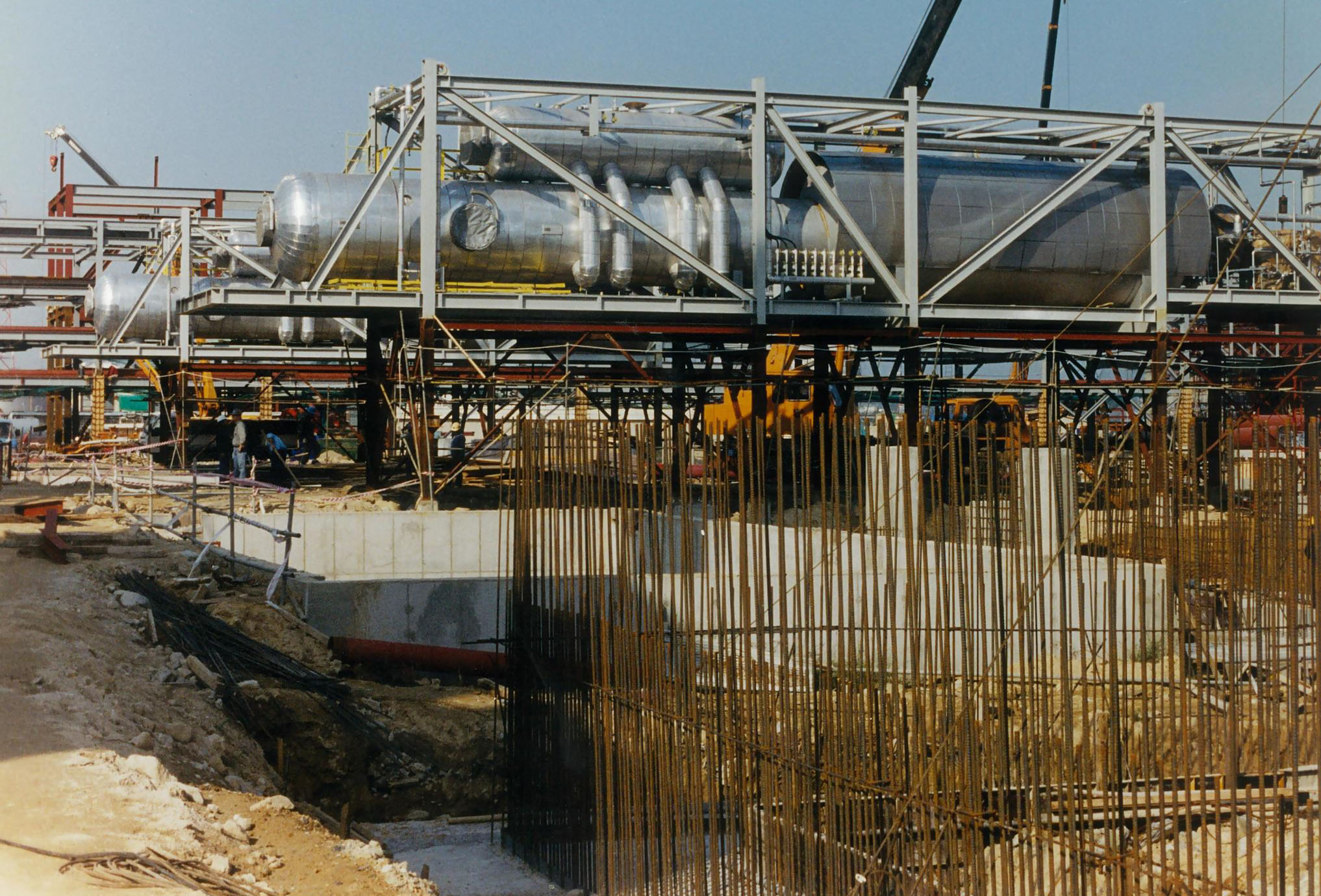
Howe Baker’s Claus Sulfur Recovery Unit design features include the following:
Proprietary Burner & Controls
- Howe Baker personnel have been designing and supplying various modifications of this burner for decades to SRU facilities around the world.
- The Proprietary Howe Baker Claus SRU Burner features a bolted design that allows burner ring replacement by field maintenance personnel within one-day after receipt of a spare burner ring. This replaceable ring design allows for quick replacement with a new burner ring designed for any future operation conditions.
- The Proprietary Howe Baker Claus SRU Burner is not limited to the small (15 psi) differential design pressure between the internal chambers as with other ring style burners that can take 3-4 weeks duration for a fabricator to dissemble, repair or replace the burner ring.
- An Advanced Control system provides reliable control of the acid gas and combustion air flows which assists with maintaining desired H2S/SO2 ratio for proper unit operation. Tail gas analysis results feedback to automatically correct for acid gas composition changes. COS analysis can also be provided.
- E2T brand infrared pyrometers are offered for reliably monitoring the Thermal Reactor temperature. Thermocouples are used only for short periods during refractory dry-out.
Two-color Howe Baker flame detectors are used for SRU Burner/Thermal Reactor flame detection. The combined ultraviolet and infrared detectors reliably detect burning of fuel gas, amine acid gas and sour water stripper gas. Fiber-optics are used to permit the location of the flame detectors away from the burner front, thus providing a less obstructed view through the burner view port. - Howe Baker provides instrument nozzle purges to keep optical sight paths of the flame scanners, infrared pyrometers and sight ports clear. The purge rotameters are grouped together to provide convenient access. Dual nitrogen/instrument air purge medias conserve nitrogen during normal operation.
Howe Baker provides transmitters for shutdown initiators. They provide improved reliability (mean time between failures) and do not require testing as frequently as switches.
SRU Overpressure Design
The SRU must be designed to protect equipment from over pressure in case of a catastrophic failure of the SRU Boiler/WHE tube or tubesheet. There are many technical papers and discussions concerning SRU relief systems. These discussions range from doing nothing and letting the overpressure balance out between parallel SRU or relieving through the TGTU to installing relief valves on each sulfur seal. Historically, relief path through the seal legs was used; however, this concept had a flaw. During normal operation, the SRU catalytic beds could become partially plugged with soot and/or sulfur restricting the flow path. This required that the total flow would need to be relieved through the No. 1 Seal Leg, requiring an oversize seal leg, or a relief device installed downstream of the No 1 Sulfur Condenser path. Installation of any type of relief device, rupture plate or relief valve, at this location would be unreliable for protecting the SRU equipment from being over pressurized due to the potential plugging with solid sulfur
Howe Baker can provide our SRU Relief Protection System which consists of pressure relief on the air blower discharge line. Howe Baker personnel have evaluated many relief options over the years and have developed a reliable, maintainable and safe relief system to protects the SRU equipment from over pressure. The Howe Baker SRU Relief System consists of a rupture disc and pressure control valve installed on the combustion air line close to the SRU Burner. This installation is located in a clean service area that will be reliable when needed. If a catastrophic failure ever occurs, the system pressure will cause the amine acid gas and combustion air flow to reduce below the low flow limit, thus shutting down the SRU. The vapors being relieved will be essentially all water vapors that can be released directly to the atmosphere at a safe location or can be routed to the Incinerator.
Other types of over pressurization systems require:
- Relief devices installed in severe service locations that can be unreliable.
- Oversize jacketed piping for the relief pass to the Incinerator.
- Possible exposure of hot liquid sulfur.
- Possible damage to other units; Incinerator, TGTU, Caustic Scrubber, etc.
Sulfur Collection Header
The Howe Baker sulfur collection header design includes horizontal steam jacketed sulfur pumps that can be maintained without shutting down SRU operation to repair a typical sump pump installed in a sulfur collection header. Also, by installing the SRU Relief Protection System, the piping system from the sulfur collection header to the incinerator only needs to be sized for the sweeping of the sulfur collection header and not sized to flow the entire quantity of gas flow during a catastrophic failure of the SRU Boiler/WHE tube rupture or tubesheet failure case. With a closed above ground sulfur storage tank located near the sulfur collection header, the air sweep system for the two pieces of equipment can be combined into a single air sweep system thus eliminating redundant piping and equipment. The air sweep will be routed to the Incinerator; however, Howe Baker can provide a system to route the sweep gas to the SRU burner for reprocessing and reducing the Incinerator emissions.
Sulfur Collection Header
Due to the removal of SWS gas from the SRU, Howe Baker can design a thermal reactor that is smaller and shorter than a replacement in kind thermal reactor. This enables the system to process the maximum amount of amine gas with no increases in the reactor footprint (Note: with SWS gas, the reactor needed to increase in size to obtain increased efficiency).
Howe Baker can provide liquid sulfur degassing via mechanical or catalytic (air injection) means. This system can be added to the Howe Baker Sulfur Collection Header design.
Sulfur Entrainment Separator in the Sulfur Condenser outlet plenums can be provided to prevent liquid sulfur carryover. The impingement style separator is designed for high removal efficiency and is installed in the vapor outlet space of the sulfur condenser plenum. This style of separator is easily serviceable.
Individual Indirect Reheat Exchangers are provided to heat the process gas from the sulfur condenser. Individual reheat exchangers provide better temperature control and improved unit operation over other types of reheat designs. Using indirect reheat permits smaller downstream equipment and eliminates any plugging of the catalyst bed caused by soot formation from a direct reheat design.
